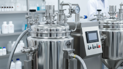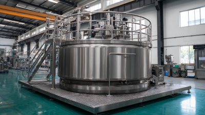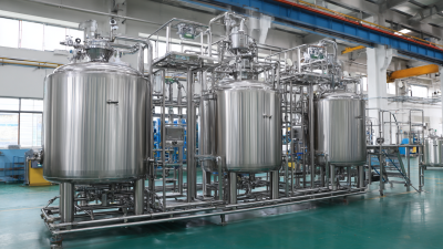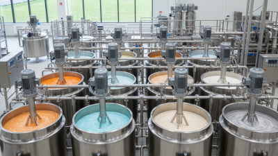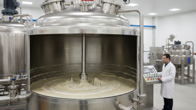
Choosing the right mixing equipment affects product quality, operating cost, and production reliability. An Agitator Mixer Tank offers controlled movement inside a vessel, helping operators blend liquids, suspend solids, or maintain uniform temperatures. Its value depends on process conditions, not appearance alone.
In practical process reviews, engineers examine viscosity, density, batch size, and required mixing time. They also consider impeller design, shaft speed, baffles, motor torque, and tank geometry. A low-viscosity liquid may need gentle circulation. A thick slurry may demand stronger torque and a carefully selected blade. Small details matter.
Cleaning access matters too.
Material compatibility should be verified before purchase. Stainless steel may suit many hygienic applications, while seals and coatings require separate review. Engineers should confirm temperature limits, corrosion resistance, drainability, and inspection requirements. These checks support safer, more repeatable operation.
An Agitator Mixer Tank can reduce settling, improve batch consistency, and simplify process control. However, it is not automatically the best solution. Excessive shear can damage sensitive products. Poorly positioned baffles can create dead zones. An oversized motor can increase energy use without improving results.
That mistake is common.
Reliable selection combines supplier documentation, process trials, and measurable acceptance criteria. A pilot test can reveal vortex formation, foaming, mixing uniformity, and cleaning challenges before full-scale installation. Operators should also review maintenance access and spare-part availability. The final decision should reflect both present needs and future production changes. Some assumptions may still prove wrong, so monitoring performance after installation remains essential.
Why Choose an Agitator Mixer Tank?
What Is an Agitator Mixer Tank, and How Does It Work?
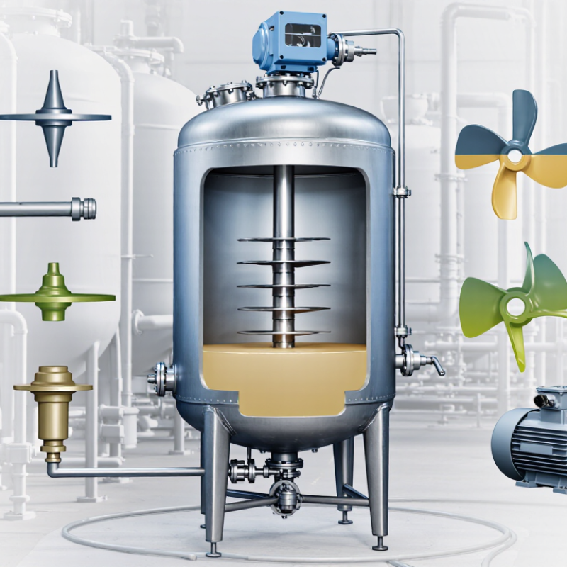
An agitator mixer tank is a vessel designed to blend liquids, powders, or suspended solids evenly. Inside, a motor turns a shaft connected to an impeller. The impeller creates controlled movement through the tank. This movement reduces settling, improves heat transfer, and distributes ingredients throughout the batch.
The tank may include baffles, a heating jacket, temperature sensors, and a sealed cover. Baffles stop the liquid from spinning as one body. Instead, they direct energy downward and across the vessel. A low-speed impeller suits thick products, while a high-speed design helps disperse lighter powders. Selecting the wrong impeller can leave dead zones.
In practical plant work, operators watch more than motor speed. They check viscosity, fill level, mixing time, and product temperature. A sample taken from the top may look uniform while the bottom remains poorly blended. That mistake is easy to miss. Testing several sampling points gives more dependable results.
Agitator tanks also support repeatable production. Automated controls can record speed, temperature, and operating time. However, automation does not replace sound process testing. Foam, heat-sensitive ingredients, and changing batch sizes may require adjustment. A mixer that performs well with water may struggle with syrup or cream. That limitation deserves attention before equipment selection.
Why Choose an Agitator Mixer Tank?
A Reynolds number above 10,000 usually signals turbulent mixing in a baffled agitator tank. The relationship is Re = ρND²/μ. Density, speed, impeller diameter, and viscosity all matter. Turbulence reduces stagnant zones and spreads heat, solids, and additives faster. However, Re is not a guarantee. Impeller shape, tank geometry, and baffle design can change actual performance. Some batches still behave badly.
The IEA’s Energy Efficiency 2023 report estimates that industry uses about 37% of global final energy. The U.S. Department of Energy also identifies motor-driven systems as major industrial electricity consumers. Therefore, selecting an agitator requires more than chasing high speed. Above 10,000 Reynolds numbers, power demand can rise sharply because power roughly follows N³. A small speed increase may create a large energy penalty. This is where pilot testing earns its cost. The calculation looks simple. The vessel is not.
Tips: Check viscosity at real process temperature, not room temperature. Confirm the Reynolds number at startup and full production. Measure torque, mixing time, and temperature uniformity. Use a calibrated sensor when possible. Industry guidance from the American Institute of Chemical Engineers supports testing scale-up assumptions rather than relying on ideal laboratory data. A useful target is consistent quality with the lowest practical speed, not maximum turbulence.
Why Choose an Agitator Mixer Tank?
Why 0.1–10 kW/m³ Power Density Matters for Tank Performance
Power density describes how much mixing energy reaches each cubic metre of liquid. The range of 0.1–10 kW/m³ covers very different process demands. At the lower end, gentle blending can protect fragile particles and reduce vortex formation. Higher values may improve gas dispersion, heat transfer, or suspension of heavy solids.
The correct number depends on viscosity, density, tank geometry, and impeller design. A clear liquid may mix well at modest power. A thick slurry can still develop dead zones at the same setting. Watch the bottom. Solids collecting there usually signal insufficient local circulation, not simply low motor size.
Field checks should include mixing time, temperature uniformity, motor load, and visible surface movement. A larger motor is not automatically better. Excessive power can create foam, shear-sensitive damage, and unnecessary operating costs. It can also hide poor baffle placement or an unsuitable impeller.
Scale-up requires care. Matching kW/m³ alone may not reproduce the same flow pattern. Tip speed, Reynolds number, and gas loading can change the result. Pilot testing is often worthwhile, even when the calculation appears convincing. Small assumptions matter. A practical design leaves room for changing viscosity, batch volume, and solids concentration. Performance should be verified under real operating conditions, not only during water trials.
Power density directly links agitator shaft power to tank volume. The chart below shows the calculated shaft power required for a 1 m³ tank at power densities from 0.1 to 10 kW/m³.
Higher power density generally provides stronger circulation, faster blending, and improved suspension of solids, while also increasing energy consumption and mechanical load. For any tank volume, the estimated shaft power can be calculated as: Power (kW) = Power Density (kW/m³) × Tank Volume (m³).
Why Choose an Agitator Mixer Tank?
How Impeller Selection Controls 1–3 Vessel-Volume Turnover Rates
An agitator mixer tank can deliver controlled circulation, heat transfer, and suspension in one vessel. The impeller largely determines how quickly liquid moves through the tank. A turnover rate of one vessel volume per minute means the impeller circulates flow equal to the working volume each minute. Three-volume turnover creates stronger circulation, but it does not guarantee uniform mixing.
Axial-flow impellers usually move liquid from the top toward the bottom, supporting whole-vessel circulation. They often suit low to medium viscosity liquids and help maintain suspended particles. Radial-flow designs create stronger local shear and may benefit gas dispersion or difficult blending zones. However, excessive shear can damage delicate materials. Tank diameter, liquid height, baffles, speed, and impeller diameter also change the result.
Small details matter.
In practical trials, operators should measure mixing time, not only motor speed. A higher speed may increase turnover while creating foam, heat, or unwanted vortexing. I have seen designs appear efficient on paper but perform poorly after viscosity changes during processing. That is why pilot testing remains valuable. Use realistic liquid properties, working volume, and temperature conditions. A 1–3 vessel-volume target should be treated as a design range, not a promise. The best impeller is the one that provides dependable circulation without wasting energy or overstressing the product.
Why Choose an Agitator Mixer Tank?
An agitator mixer tank can turn uneven heating into a controlled process. The U.S. Energy Information Administration reports that process heating represented about 51% of manufacturing energy use in 2018. Better circulation can reduce cold spots near tank walls and hot zones around heating coils. That matters when a batch contains viscous liquid, crystals, or temperature-sensitive ingredients. In practice, operators often find deposits first at the bottom outlet. Poor mixing is usually the cause.
Solids suspension is another strong reason. A properly selected impeller keeps particles moving above the tank floor. It also reduces settling during transfer or short production pauses. Perry’s Chemical Engineers’ Handbook links suspension performance with impeller speed, liquid properties, particle size, and tank geometry. More speed is not always better. Excessive speed can increase shear, foaming, and energy demand. A 2022 U.S. Department of Energy roadmap identifies process heat as a major industrial energy burden, so inefficient agitation deserves careful review.
Scale-up needs measured evidence. Engineers should compare power per volume, tip speed, mixing time, and the minimum suspension speed. A pilot tank may look successful while hiding a full-scale dead zone. That assumption is convenient, but not always right. Trial runs should record torque, temperature at several heights, and solids concentration over time. Real tanks are messier. A modest design change, such as a wider impeller or better baffles, can sometimes improve uniformity more than a larger motor.
Typical preliminary-design comparison for liquid mixing, thermal processing, and solids-handling applications.
| Agitator Configuration | Typical Process Duty | Practical Liquid Viscosity Range | Heat-Transfer Performance | Solids-Suspension Capability | Typical Scale-Up Basis | Key Design Consideration |
|---|---|---|---|---|---|---|
| Low-speed anchor with wall scrapers | High-viscosity blending, crystallization, thermal holding, and batch products requiring strong wall turnover | 1–100 Pa·s Application-dependent |
High for viscous fluids Scrapers renew the boundary layer at the vessel wall and reduce stagnant regions near the heat-transfer surface. |
Low to moderate Suitable when solids are fine, light, or supported by secondary mixing elements. |
Maintain comparable wall-shear conditions, scraper clearance, and torque per unit volume. | High drive torque; requires careful mechanical design and adequate clearance for thermal expansion. |
| Axial-flow pitched-blade turbine | General-purpose blending, liquid–liquid mixing, moderate solids suspension, and temperature equalization | 0.001–5 Pa·s Water-like to moderately viscous liquids |
Good Promotes bulk circulation through the full tank volume and improves contact between the liquid and heat-transfer surfaces. |
Good Commonly selected for maintaining coarse or dense solids above the vessel bottom. |
Maintain power per unit volume or circulation requirements, while checking tip speed and blend time. | May require baffles to limit vortexing; multiple impellers may be needed in tall tanks. |
| Hydrofoil axial-flow impeller | Low-shear blending, solids suspension, heat distribution, and energy-efficient circulation | 0.001–2 Pa·s Low to moderate viscosity |
Good High pumping capacity at relatively low shear can improve tank-wide circulation and reduce thermal stratification. |
Very good Efficient for off-bottom suspension when properly sized and positioned. |
Match dimensionless pumping and power characteristics; preserve impeller-to-tank and impeller-to-bottom ratios. | Less suitable for highly viscous products or applications needing intense dispersion. |
| Radial-flow turbine | Gas dispersion, liquid–liquid dispersion, and processes requiring higher local shear | 0.001–1 Pa·s Low-viscosity liquids |
Moderate Provides strong local turbulence, but whole-tank circulation may be lower than with axial-flow designs. |
Moderate Can suspend solids locally; vessel geometry and impeller placement strongly affect bottom coverage. |
Maintain power per unit volume, gas-flow ratio, and similar geometric proportions. | Higher shear and power demand; baffles are normally required to control swirl. |
| High-shear rotor–stator | Powder wet-out, emulsification, deagglomeration, and rapid dispersion of difficult ingredients | 0.001–10 Pa·s Depends on formulation and temperature |
Localized improvement Generates intense local mixing but does not replace bulk circulation for uniform tank heating. |
Very good for deagglomeration Effective for breaking agglomerates; continuous suspension may require a separate main agitator. |
Scale by tip speed, flow-through capacity, energy density, and residence time—not simply geometric size. | Higher shear, noise, and power density; can increase air entrainment or product temperature. |
| Dual-impeller system | Tall tanks, large working volumes, broad viscosity range, and simultaneous heat transfer and solids suspension | 0.001–20 Pa·s With suitable impeller selection |
Very good Separate upper and lower circulation zones can reduce thermal gradients and dead zones. |
Very good Lower impeller supports bottom suspension while the upper impeller improves overall turnover. |
Maintain impeller spacing, power per volume, blend-time target, and hydraulic coverage as scale changes. | More complex shaft dynamics, increased cost, and greater need for adequate tank height-to-diameter analysis. |
| No mechanical agitation | Simple storage of low-viscosity liquids with minimal composition or temperature variation | Below 0.01 Pa·s Only for applications tolerant of stratification |
Low Natural convection alone may be insufficient for uniform temperature in larger or insulated tanks. |
Poor Settling, sediment compaction, and concentration gradients are likely when solids are present. |
Scale-up is limited because natural circulation and settling behavior change with tank size. | Lowest equipment cost, but often unsuitable for controlled heat transfer, uniformity, or repeatable batch quality. |
Values are representative preliminary-design ranges, not guaranteed operating limits. Final selection should be confirmed using fluid rheology, solids particle size and density, heat-transfer area, vessel geometry, required blend time, power availability, and mechanical-load calculations.
Common engineering scale-up criteria: power per unit volume, impeller tip speed, pumping capacity, blend time, off-bottom suspension speed, heat-transfer coefficient, and geometric similarity.